
Embark on a journey into the intricate world of blueprints with Blueprints Level 2 Lesson 7, where you’ll unravel the mysteries of architectural design. This lesson will guide you through the fundamentals of reading and interpreting blueprints, empowering you to understand the language of construction.
From deciphering the different types of lines and symbols to comprehending the importance of scale and dimensioning, this lesson provides a comprehensive overview of the essential elements of blueprints. You’ll discover how to create and interpret floor plans, elevations, sections, and details, gaining invaluable insights into the design and construction process.
Understanding Blueprints Level 2 Lesson 7
Blueprints Level 2 Lesson 7 delves into the complexities of interpreting and utilizing architectural blueprints. This lesson equips learners with the essential knowledge and skills to decipher these technical drawings, empowering them to understand the design intent, construction methods, and material specifications of buildings.
The lesson covers a comprehensive range of topics, including:
Key Concepts
- Blueprint symbols and conventions
- Understanding scale and dimensions
- Interpreting floor plans, elevations, and sections
- Reading construction notes and specifications
li>Identifying structural components and materials
Building and Interpreting Blueprints
Blueprints are technical drawings that provide detailed instructions for constructing buildings and other structures. They are essential tools for architects, engineers, and contractors, as they allow them to communicate their designs clearly and accurately.
Reading and interpreting blueprints can be a challenging task, but it is essential for anyone involved in the construction industry. The process involves understanding the different types of lines and symbols used in blueprints, as well as the overall layout and organization of the drawings.
Types of Lines and Symbols
Blueprints use a variety of lines and symbols to represent different elements of a building. These lines and symbols are standardized, so that they can be easily understood by anyone who is familiar with blueprint reading.
- Solid linesrepresent the visible edges of a building.
- Dashed linesrepresent hidden edges or objects that are not visible from the front.
- Dotted linesrepresent center lines or reference lines.
- Circlesrepresent columns or other round objects.
- Squaresrepresent walls or other rectangular objects.
- Trianglesrepresent doors or windows.
Common Blueprint Symbols, Blueprints level 2 lesson 7
In addition to lines, blueprints also use a variety of symbols to represent specific elements of a building. These symbols are also standardized, so that they can be easily understood by anyone who is familiar with blueprint reading.
| Symbol | Meaning |
|---|---|
 |
Door |
 |
Window |
 |
Staircase |
 |
Elevator |
 |
Toilet |
Design and Dimensioning
Blueprints serve as the blueprint for constructing structures. They include crucial details on the design and dimensions of the structure, which are essential for builders and engineers to follow. Understanding the significance of scale and dimensioning is essential when interpreting blueprints.
Scale and Dimensioning
Scale refers to the ratio between the dimensions on the blueprint and the actual dimensions of the structure. It helps users understand the size and proportions of the structure. Dimensioning, on the other hand, provides specific measurements for various elements of the structure, such as walls, windows, and doors.
These measurements are crucial for accurate construction and assembly.
Calculating Dimensions
To calculate dimensions from blueprints, one must first determine the scale of the drawing. The scale is typically indicated on the blueprint itself. Once the scale is known, measurements can be calculated by multiplying the blueprint dimensions by the scale factor.
Types of Dimensions
- Overall Dimensions:Indicate the overall size and shape of the structure.
- Linear Dimensions:Provide measurements for the length, width, and height of specific elements.
- Radial Dimensions:Used for circular or curved elements, indicating the radius or diameter.
- Angular Dimensions:Specify the angles between different elements.
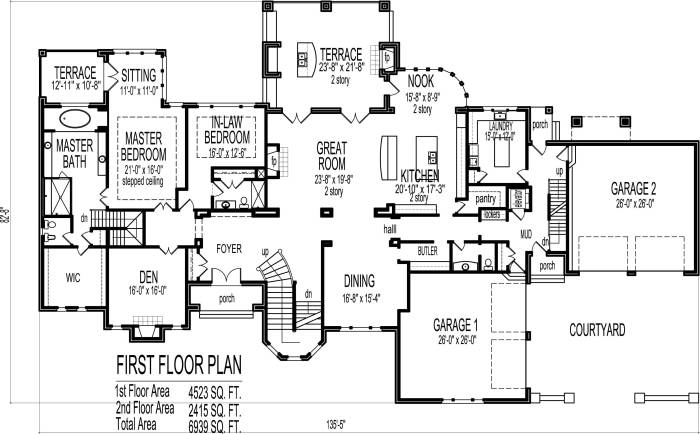
Floor Plans and Elevations
Floor plans and elevations are two essential types of blueprints that provide detailed information about a building’s design and dimensions. Floor plans show the layout of a building from above, while elevations show the exterior walls of a building from the side.
Types of Floor Plans
- Architectural Floor Plans:Show the overall layout of a building, including walls, doors, windows, and other architectural features.
- Structural Floor Plans:Focus on the structural elements of a building, such as beams, columns, and foundations.
- Mechanical Floor Plans:Show the location of mechanical systems, such as plumbing, electrical, and HVAC.
- Finish Floor Plans:Detail the finishes and materials used in a building, such as flooring, countertops, and paint colors.
Creating and Interpreting Floor Plans
To create a floor plan, architects use a scale to represent the actual dimensions of a building. They then draw the walls, doors, windows, and other features to scale. To interpret a floor plan, it is important to understand the scale and the symbols used to represent different features.
Types of Elevations
- Front Elevation:Shows the front exterior wall of a building.
- Rear Elevation:Shows the rear exterior wall of a building.
- Side Elevations:Show the left and right exterior walls of a building.
- Interior Elevations:Show the interior walls of a building, including doors, windows, and other features.
Uses of Elevations
Elevations are used to show the height and shape of a building, as well as the location of windows, doors, and other exterior features. They can also be used to calculate the amount of materials needed to construct a building.
Sections and Details
Sections and details are critical components of blueprints, providing in-depth information about specific areas or elements of a building design. They allow architects and builders to visualize and understand the construction’s intricate details.
Creating sections involves cutting through the building model at specific points to reveal its internal structure. These sections provide insights into the arrangement of rooms, walls, ceilings, and other architectural features. Details, on the other hand, are enlarged drawings that focus on particular aspects of the design, such as door and window details, electrical outlets, and plumbing fixtures.
Interpreting Sections and Details
Interpreting sections and details requires a keen eye and an understanding of architectural symbols and conventions. Sections are typically represented by a vertical or horizontal cut through the building, while details are shown as separate drawings with enlarged scales. By carefully examining these drawings, architects and builders can determine the exact dimensions, materials, and construction methods used in the design.
Types of Sections and Details
There are various types of sections and details commonly used in blueprints. Some common examples include:
- Cross-sections:Cut vertically through a building, showing the relationship between different floors and spaces.
- Longitudinal sections:Cut horizontally through a building, revealing the length and layout of rooms and spaces.
- Details of door and window openings:Provide specific dimensions, materials, and hardware requirements for doors and windows.
- Details of electrical outlets and plumbing fixtures:Indicate the location, type, and specifications of electrical outlets, switches, and plumbing fixtures.
- Details of wall construction:Show the layers of materials used in wall construction, including insulation, drywall, and siding.
These sections and details are essential for ensuring the accuracy and completeness of blueprints, facilitating effective communication between architects, builders, and other stakeholders involved in the construction process.
If you’re tackling Blueprints Level 2 Lesson 7, you’re on the right track! For a little break, why not check out Abeka Spanish 1 Test 11 ? It’s a great way to test your language skills. Once you’ve refreshed your Spanish, come back to Blueprints Level 2 Lesson 7 with renewed vigor.
You got this!
Additional Topics: Blueprints Level 2 Lesson 7
In addition to the core concepts covered in Blueprints Level 2 Lesson 7, the lesson also delves into several additional topics that enhance the understanding of blueprint reading and interpretation.
These topics include:
Symbols and Abbreviations
Blueprints use a standardized set of symbols and abbreviations to represent various elements and features. Understanding these symbols is crucial for accurately interpreting the plans.
Building Codes and Regulations
Blueprints must adhere to specific building codes and regulations that ensure the safety and functionality of the structure. Lesson 7 provides an overview of these codes and their impact on blueprint design.
Material Specifications
Blueprints specify the materials used in the construction of the building, including their dimensions, properties, and performance requirements. This information is essential for ensuring the durability and longevity of the structure.
Construction Details
Lesson 7 covers various construction details, such as framing systems, insulation techniques, and roofing systems. Understanding these details is necessary for visualizing the building’s physical structure and ensuring proper construction practices.
Site Plans
In addition to floor plans, elevations, and sections, blueprints may also include site plans. Site plans provide an overview of the building’s location, surrounding environment, and landscaping features.
Frequently Asked Questions
What is the purpose of Blueprints Level 2 Lesson 7?
Blueprints Level 2 Lesson 7 aims to provide a thorough understanding of the principles of blueprint reading and interpretation, empowering individuals to comprehend the language of architectural design.
What are the key concepts covered in this lesson?
The lesson delves into the process of reading and interpreting blueprints, explaining the different types of lines and symbols used. It also covers the importance of scale and dimensioning, as well as the creation and interpretation of floor plans, elevations, sections, and details.
Who can benefit from this lesson?
Blueprints Level 2 Lesson 7 is suitable for aspiring architects, homeowners planning renovations, and anyone interested in gaining insights into the design and construction process.
